- 您现在的位置:买卖IC网 > Sheet目录362799 > EV2365DN-00A (Monolithic Power Systems, Inc.) 3A, 28V, 1.4MHz Step-Down Converter
MP2365 – 3A, 28V, 1.4MHz STEP-DOWN CONVERTER
MP2365 Rev. 0.91
7/10/2006
www.MonolithicPower.com
9
MPS Proprietary Information. Unauthorized Photocopy and Duplication Prohibited.
2006 MPS. All Rights Reserved.
To optimize the compensation components for
conditions not listed in Table 3, the following
procedure can be used.
1. Choose the compensation resistor (R3) to set
the desired crossover frequency. Determine the
R3 value by the following equation:
FB
OUT
V
CS
EA
C
V
G
G
f
2
C
×
2
3
R
×
×
×
π
=
Where f
C
is the desired crossover frequency.
2. Choose the compensation capacitor (C3) to
achieve
the
desired
applications with typical inductor values, setting
the compensation zero, f
Z1
, below one forth of the
crossover frequency provides sufficient phase
margin. Determine the C3 value by the following
equation:
phase
margin.
For
C
f
3
R
2
4
3
C
×
×
π
>
3. Determine if the second compensation
capacitor (C6) is required. It is required if the ESR
zero of the output capacitor is located at less than
half of the 1.4MHz switching frequency, or the
following relationship is valid:
2
f
R
2
C
2
1
S
ESR
<
×
×
π
If this is the case, then add the second
compensation capacitor (C6) to set the pole f
P3
at the location of the ESR zero. Determine the
C6 value by the equation:
3
R
R
2
C
6
C
ESR
×
=
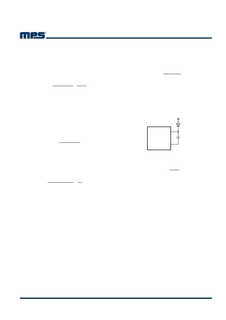
External Bootstrap Diode
It is recommended that an external bootstrap
diode be added when the system has a 5V
fixed input or the power supply generates a 5V
output. This helps improve the efficiency of the
regulator. The bootstrap diode can be a low
cost one such as IN4148 or BAT54.
MP2365
SW
BS
10nF
5V
Figure 2—External Bootstrap Diode
This diode is also recommended for high duty
cycle operation (when
IN
OUT
V
V
>65%) and high
output voltage (V
OUT
>12V) applications.
发布紧急采购,3分钟左右您将得到回复。
相关PDF资料
EV2365DN-01A
3A, 28V, 1.4MHz Step-Down Converter Evaluation Board
EV2995-10
G2995 Evaluation Board Manual
EVG2995
G2995 Evaluation Board Manual
EV3011DQ-00A
1x, 1.5x, 2x High Efficiency Charge Pump 2 White LED Driver Evaluation Board
EV3204DJ-00A
Fixed Frequency White LED Driver
EV3205DJ-00A
1.3MHz Fixed Frequency 5 White LED Driver
EV3213DH-00A
700KHz/1.3MHz Boost Converter with a 3.5A Switch
EV4101
32-bit Microprocessor that Executes MIPS I,a Subset of MIPS II,and a Subset of the MIPS16 Instructions.(32位微处理器(执行MIPS I,MIPS II的子集,MIPS16的子集指令))
相关代理商/技术参数
EV2365DN-01A
制造商:MPS 制造商全称:Monolithic Power Systems 功能描述:3A, 28V, 1.4MHz Step-Down Converter Evaluation Board
EV24-0.5-02-44M
功能描述:共模滤波器/扼流器 44mH 0.5A - VERTICAL COMMN-MODE SPPRESSN RoHS:否 制造商:TDK 电感: 阻抗:35 Ohms 容差: 最大直流电流:0.1 A 最大直流电阻:1.5 Ohms 自谐振频率: Q 最小值: 工作温度范围:- 25 C to + 85 C 端接类型:SMD/SMT 封装 / 箱体:0302 (0806 metric) 系列:TCE
EV24-0.5-02-44M-1
功能描述:共模滤波器/扼流器 44mH 0.5A - VERTICAL COMMN-MODE SPPRESSN RoHS:否 制造商:TDK 电感: 阻抗:35 Ohms 容差: 最大直流电流:0.1 A 最大直流电阻:1.5 Ohms 自谐振频率: Q 最小值: 工作温度范围:- 25 C to + 85 C 端接类型:SMD/SMT 封装 / 箱体:0302 (0806 metric) 系列:TCE
EV24-0.8-02-18M
功能描述:共模滤波器/扼流器 18mH 0.8A - VERTICAL COMMN-MODE SPPRESSN RoHS:否 制造商:TDK 电感: 阻抗:35 Ohms 容差: 最大直流电流:0.1 A 最大直流电阻:1.5 Ohms 自谐振频率: Q 最小值: 工作温度范围:- 25 C to + 85 C 端接类型:SMD/SMT 封装 / 箱体:0302 (0806 metric) 系列:TCE
EV2400
功能描述:界面开发工具 EV2400 Eval Mod Interface Board RoHS:否 制造商:Bourns 产品:Evaluation Boards 类型:RS-485 工具用于评估:ADM3485E 接口类型:RS-485 工作电源电压:3.3 V
EV2400
制造商:Texas Instruments 功能描述:EVAL BOARD EV2400 USB INTERFACE
EV24-1.0-02-10M
功能描述:共模滤波器/扼流器 10mH 1A - VERTICAL COMMN-MODE SPPRESSN RoHS:否 制造商:TDK 电感: 阻抗:35 Ohms 容差: 最大直流电流:0.1 A 最大直流电阻:1.5 Ohms 自谐振频率: Q 最小值: 工作温度范围:- 25 C to + 85 C 端接类型:SMD/SMT 封装 / 箱体:0302 (0806 metric) 系列:TCE
EV24-1.5-02-4M5
功能描述:共模滤波器/扼流器 4.5mH 1.5A -VERTICAL COMMN-MODE SPPRESSN RoHS:否 制造商:TDK 电感: 阻抗:35 Ohms 容差: 最大直流电流:0.1 A 最大直流电阻:1.5 Ohms 自谐振频率: Q 最小值: 工作温度范围:- 25 C to + 85 C 端接类型:SMD/SMT 封装 / 箱体:0302 (0806 metric) 系列:TCE